Welcome to the Cosco Scenera Instruction Manual, your comprehensive guide to safe and effective use of the Cosco Scenera NEXT Convertible Car Seat․
This manual provides detailed instructions, safety precautions, and technical specifications to ensure your child’s protection and comfort while traveling․
Safety First: Always read and follow the warnings and guidelines to avoid serious consequences and ensure proper installation and usage․
Discover how to maximize your car seat’s potential with step-by-step instructions, troubleshooting tips, and maintenance advice for optimal performance and longevity․
1․1 Overview of the Cosco Scenera Car Seat
The Cosco Scenera NEXT Convertible Car Seat is a versatile and reliable child restraint designed for safety and comfort․ It accommodates children from 5 to 40 pounds, offering both rear-facing and forward-facing options․ Known for its lightweight and compact design, it is ideal for small vehicles or families needing multiple car seats․ The seat features a 10-year expiration date from the manufacture date, ensuring long-term usability․ This manual provides essential guidance for proper installation, adjustment, and maintenance to ensure your child’s safety and comfort during travel․
Key Details: The Cosco Scenera NEXT is designed for easy installation using LATCH or seat belt, with a focus on safety and durability․ Always refer to the manual for specific instructions․
1․2 Importance of Following the Instruction Manual
Following the Cosco Scenera instruction manual is critical for ensuring your child’s safety and proper use of the car seat․ The manual provides detailed guidance on installation, adjustment, and maintenance, all of which are essential for maximizing protection․ Failure to follow the instructions can result in improper installation, leading to potential safety hazards․ Adhering to the guidelines ensures compliance with safety standards and prevents serious consequences․ By carefully reading and following the manual, you can guarantee your child’s comfort and security while traveling․ Always prioritize your child’s safety by strictly following the provided instructions․
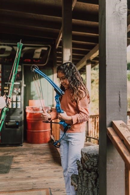
1․3 Key Features of the Cosco Scenera NEXT Convertible Car Seat
The Cosco Scenera NEXT Convertible Car Seat is designed with safety and convenience in mind․ It features a lightweight and compact design, making it easy to transfer between vehicles․ The seat supports both rear-facing and forward-facing configurations, accommodating children from 5 to 40 pounds․ It includes a 5-point harness for secure restraint and adjustable headrest for growing children․ The seat also has a built-in cup holder for added convenience․ Its convertible design ensures long-term use, adapting to your child’s needs as they grow․ These features make it a practical and reliable choice for parents seeking a safe and durable car seat solution․

Safety Guidelines and Warnings
Always read the instruction manual carefully before using the Cosco Scenera car seat․ Failure to follow warnings can result in serious injury or harm to your child․
Safety Guidelines: Ensure proper installation, secure the child with the harness, and avoid modifying the seat․ Regular inspections are crucial for safe operation․
2․1 General Safety Precautions
Always follow the Cosco Scenera instruction manual to ensure your child’s safety․ Proper installation and use are critical to prevent accidents․ Regularly inspect the seat for damage or wear․ Avoid using unauthorized accessories, as they may compromise safety․ Never modify the car seat or use it for children beyond the recommended weight or height limits․ Ensure the child is correctly secured with the harness, and the seat is tightly fastened in the vehicle․ Failure to adhere to these precautions can lead to serious risks․ Keep the manual handy for reference and update yourself on any safety recalls or updates․
2․2 Warning Labels on the Car Seat
The Cosco Scenera car seat features essential warning labels that highlight critical safety information․ These labels are strategically placed on the seat and in the manual to ensure visibility․ They cover key points such as proper installation, correct harness usage, and weight/height limits․ The labels also emphasize the dangers of improper use, like rear-facing without the base or using unauthorized accessories․ Always check these warnings before and during use to guarantee your child’s safety․ They serve as vital reminders to follow the manual and maintain the seat’s integrity for effective protection․
2․3 Consequences of Not Following Instructions
Failing to follow the Cosco Scenera instruction manual can lead to serious safety risks․ Improper installation or incorrect use of the car seat may result in inadequate protection during an accident, increasing the risk of injury or harm to the child․ Misuse can also void the product warranty and compromise its structural integrity․ Always adhere to the guidelines to ensure optimal safety and performance․ Ignoring instructions may lead to legal consequences and potential harm, emphasizing the importance of strict compliance with the provided instructions․
Installation and Assembly
This section guides you through the installation and assembly of the Cosco Scenera car seat․ It covers unpacking, preparation, and step-by-step instructions for secure installation․ Proper assembly ensures safety and correct functionality, so follow the manual carefully to avoid errors․
3․1 Unpacking and Preparing the Car Seat
Begin by carefully unpacking the Cosco Scenera car seat and its accessories․ Inspect the seat for any damage or missing parts․ Remove all packaging materials and ensure the seat is clean․ Familiarize yourself with the components, including the harness, buckles, and LATCH connectors․ Before installation, read the manual thoroughly to understand the assembly process․ Ensure all parts are accounted for and in good condition․ If any damage is found, do not use the seat and contact customer support immediately․ Proper preparation ensures a safe and correct installation․
3․2 Step-by-Step Installation Process
Start by selecting a suitable vehicle seat, ensuring clear access to the seat belt or LATCH anchors․ For rear-facing installation, place the car seat on the vehicle seat and align the base․ Secure it using the LATCH connectors or seat belt, tightening firmly․ For forward-facing, position the seat and attach using LATCH or the vehicle’s seat belt․ Tighten the straps until the seat is rigid․ Always refer to your vehicle’s manual for LATCH anchor locations․ Ensure the seat is level and stable․ Double-check the installation by shaking the seat gently—it should not move more than an inch side-to-side or front-to-back․ Always test the installation before placing your child in the seat․
3․3 Forward-Facing vs․ Rear-Facing Installation
The Cosco Scenera NEXT can be installed in both forward-facing and rear-facing positions․ Rear-facing is recommended for infants up to 40 pounds or 40 inches tall, as it provides better neck and spine protection․ Forward-facing is suitable for children over 40 pounds or 40 inches tall․ For rear-facing, ensure the seat is level and secured tightly using LATCH or a seat belt․ For forward-facing, attach the top tether to the vehicle’s anchor for added stability․ Always verify the seat’s level indicator and follow weight and height limits for each configuration․ Proper positioning ensures optimal safety for your child․
3․4 Using LATCH vs․ Seat Belt for Securement
For installing the Cosco Scenera NEXT, you can choose between LATCH (Lower Anchors and Tethers for Children) or a vehicle seat belt․ LATCH provides a quicker and more straightforward installation, with built-in anchors in most vehicles․ It reduces the risk of incorrect seat belt routing․ However, if your vehicle lacks LATCH anchors or they are unavailable, a seat belt offers a reliable alternative․ Both methods ensure a secure fit when done correctly․ Always follow the manual’s specific instructions for your chosen method to guarantee safety and proper installation․
3․5 Vehicle Compatibility and Seat Placement
Ensure the Cosco Scenera NEXT is compatible with your vehicle by checking the manual and your car’s owner’s guide․ The seat should be placed in the rear seat, away from active front airbags․ Never install it in side-facing or truck beds․ Choose a spot with a flat, stable surface and proper belt routing․ Avoid areas where the seat could shift or be crushed․ Test the fit in your vehicle to confirm snug placement․ Always follow the manual’s guidelines for correct positioning to ensure safety and compliance with regulations․

Adjusting and Securing the Car Seat
Adjust the harness to fit snugly, ensuring proper seat height and positioning․ Secure the child with the harness, tighten the seat belt or LATCH straps for safety․
4․1 Harness Adjustment for Proper Fit
Ensure the harness is snug and even, with straps at or below the child’s shoulders when rear-facing, and at or above when forward-facing․ Loosen the harness by pressing the release button․ Place the child in the seat and fasten the harness, ensuring it fits comfortably without twisting․ Tighten the straps until the harness feels secure․ Check the fit by attempting to pinch the strap at the shoulder; if you can’t pinch any material, the fit is correct․ Adjust the chest clip to armpit level to keep the harness properly positioned․ Regularly check and adjust as the child grows․
4․2 Adjusting the Seat Height and Position
To ensure optimal safety and comfort, adjust the seat height and position according to your child’s needs․ Use the height adjustment handle located at the back of the seat to raise or lower it․ For rear-facing, the seat should recline to a safe angle, while forward-facing requires a more upright position․ Ensure the base is flat on the vehicle seat and not tilted․ Do not use extra padding or pillows unless specified․ After adjusting, check the level indicator to confirm proper positioning․ Tighten the seat securely and test stability by gently rocking it․ Always verify the fit after adjustments; Regular checks are essential as your child grows․ Ensure proper alignment with the vehicle’s seatbelt or LATCH system for maximum safety․ Adjustments should be made with the child absent to avoid injury or improper fitting․ If unsure, consult the manual or contact customer support․ Proper positioning ensures effective crash protection and comfort during travel․ Keep the seat tightly secured to prevent movement while driving․ Avoid over-tightening, as this could cause discomfort or restrict movement․ Always refer to the Cosco Scenera manual for specific guidance tailored to your model․ Adjustments should be smooth and deliberate to maintain safety standards․ Never leave the seat unsecured or loosely fitted, as this compromises safety․ Ensure all parts are securely locked in place after adjustments․ By following these steps, you can achieve the correct seat height and position for your child’s safety and comfort․ Regular inspections are crucial to maintain proper fit and function․
4․3 Securing the Child with the Harness
Securing your child with the harness is critical for safety․ Place the child in the seat and ensure the harness straps are properly aligned over the shoulders․ The chest clip should be at armpit level, and the straps should be snug but not too tight․ Buckle the harness and tighten the straps by pulling the adjustment strap until the child is securely fitted․ Check the tightness by attempting to pinch the straps; they should not have any slack․ Ensure the harness is at or below the child’s shoulders for rear-facing and at or above for forward-facing․ Always verify that all buckles are correctly fastened and the harness is tightly secured before each use․ Regularly inspect the harness for proper fit as the child grows․ Avoid using any additional accessories that could interfere with the harness’s performance․ Proper harness security ensures maximum protection in the event of sudden stops or collisions․ Never drive without ensuring the child is correctly harnessed․ Always refer to the Cosco Scenera manual for specific guidance on harness adjustment․ Proper fit is essential for effective crash protection․ Ensure the harness is snug and even on both sides to prevent shifting during travel․ If unsure, seek assistance to ensure correct installation․ Correct harness use is vital for your child’s safety․ Always double-check the harness before each trip․ Proper harnessing ensures optimal safety and comfort for your child․
4․4 Tightening the Seat Belt or LATCH Straps
To ensure a secure installation, tighten the seat belt or LATCH straps properly․ For seat belt installation, route the belt through the designated path and buckle it․ Pull the belt firmly to remove slack, then press the car seat into the vehicle seat while tightening․ For LATCH, attach the connectors to the vehicle’s anchors and pull the straps to tighten․ After securing, check for movement by gently tugging the car seat; it should not shift more than 1 inch side-to-side or front-to-back․ Always ensure the straps are snug and even on both sides for optimal stability․ Proper tightening ensures the car seat stays firmly in place during travel․ Regularly inspect the straps for proper tension and adjust as needed․ If using a seat belt, make sure it is locked in place according to your vehicle’s instructions․ Achieving the correct tightness is essential for the car seat to function as intended in the event of sudden stops or collisions․ Always verify the tightness of the straps before each use․ Properly tightened straps ensure the car seat remains stable and secure, providing maximum protection for your child․ Follow the Cosco Scenera manual for specific tightening instructions to guarantee safety and effectiveness․ Tightening correctly is a critical step in ensuring your child’s safety while traveling․ Always double-check the straps’ tightness to ensure they are secure and properly aligned․ Proper installation and tightening are vital for the car seat to perform as designed․ Never skip this step, as it directly impacts the safety of your child․ Ensure the car seat is tightly secured to prevent any movement during travel․ Always refer to the Cosco Scenera manual for guidance on securing the car seat with seat belts or LATCH straps․ Proper tightening ensures the car seat remains stable and secure, providing maximum protection for your child․ Always double-check the straps’ tightness to ensure they are secure and properly aligned․ Proper installation and tightening are vital for the car seat to perform as designed․ Never skip this step, as it directly impacts the safety of your child․ Ensure the car seat is tightly secured to prevent any movement during travel․ Always refer to the Cosco Scenera manual for guidance on securing the car seat with seat belts or LATCH straps․

Usage and Maintenance
Regularly inspect the car seat for wear, clean fabric with mild detergent, and store it properly when not in use to maintain its safety and effectiveness․
5․1 Daily Checks Before Use
Before each use, inspect the Cosco Scenera for visible damage, ensure all straps and buckles are secure, and verify proper installation in the vehicle․ Check that the harness fits snugly around the child, with the chest clip at armpit level, and ensure the seat belt or LATCH system is tightly secured․ Look for any signs of wear or fraying on the straps and confirm the expiration date on the label․ Always ensure the child is within the weight and height limits; These daily checks are crucial for maintaining safety and ensuring the seat functions correctly in the event of sudden stops or accidents․
5․2 Cleaning the Car Seat Fabric
To clean the Cosco Scenera fabric, start by spot-cleaning stains with a mild soap solution and a soft, damp cloth․ Avoid harsh chemicals or bleach, as they may damage the material․ For tougher stains, gently scrub the area, then rinse with clean water․ Allow the fabric to air dry completely before use․ Never machine wash or submerge the seat in water, as this could compromise its safety features․ Regular cleaning helps maintain hygiene and ensures the car seat remains in good condition for your child’s safety and comfort․
5․3 Storing the Car Seat When Not in Use
When storing the Cosco Scenera car seat, ensure it is placed in a cool, dry environment, away from direct sunlight and moisture․ Avoid leaving it in a vehicle, especially in extreme temperatures․ Store the seat in its original packaging or a sturdy box to protect it from dust and damage․ Clean the seat thoroughly before storage to prevent mold or mildew․ Always check that all parts, including harnesses and straps, are included․ Proper storage ensures the car seat remains in excellent condition for future use, maintaining its safety and functionality for your child․
5․4 Regular Inspection for Wear and Tear
Regularly inspect the Cosco Scenera car seat for signs of wear and tear to ensure its safety and performance․ Check the harness straps for fraying, cracks, or abrasions, and verify that all buckles and connectors are functioning properly․ Examine the seat shell for cracks or dents and the fabric for tears or fading․ Inspect the LATCH connectors and seat belt paths for damage or debris․ If any damage is found, discontinue use and contact the manufacturer․ Cleaning and maintenance should follow the manual’s guidelines to prevent degradation․ Regular checks help maintain the seat’s integrity and ensure your child’s safety over time․

Technical Specifications
The Cosco Scenera car seat features weight and height limits, specific dimensions, durable materials, and an expiration date for safe use, ensuring reliability and compliance with safety standards․
6․1 Weight and Height Limits
The Cosco Scenera NEXT has a rear-facing weight limit of 40 pounds and 40 inches tall, while forward-facing accommodates up to 50 pounds and 50 inches tall․ These limits ensure proper fit and safety․ Always check the manual for exact specifications, as exceeding these can compromise safety․ The seat is designed to grow with your child, providing long-term protection․ Proper adherence to these limits ensures optimal performance and compliance with safety standards․ This section helps you understand the maximum capacities for safe and effective use of the car seat․
6․2 Dimensions of the Car Seat
The Cosco Scenera NEXT measures approximately 17․5 inches wide, 24 inches tall, and 15 inches deep, making it a compact option for smaller vehicles․ Its lightweight design, weighing around 11 pounds, enhances portability․ These dimensions ensure compatibility with most car models while maintaining comfort for the child․ Understanding the car seat’s size is crucial for proper installation and ensuring it fits well in your vehicle․ Always verify the exact measurements in the manual to align with your vehicle’s specifications and seating arrangement needs for optimal safety and convenience․
6․3 Material and Construction Details
The Cosco Scenera NEXT is constructed with durable, high-quality materials designed for safety and longevity․ The seat features a sturdy plastic shell, soft padding for comfort, and a robust harness system․ The materials are engineered to meet federal safety standards, ensuring protection in the event of a crash․ The lightweight design, weighing just 11 pounds, enhances portability without compromising safety․ The seat’s construction includes a metal-reinforced frame for added strength and stability․ These materials and design elements work together to provide a safe, comfortable, and reliable car seat for your child․
6․4 Expiry Date and Warranty Information
The Cosco Scenera NEXT has a 10-year expiry date from the date of manufacture, ensuring long-term use․ The warranty covers defects in materials and workmanship for one year from purchase․ For warranty claims, contact Cosco customer support with proof of purchase․ Proper registration and adherence to usage guidelines are essential for warranty validity․ Always check the expiration date on the seat and refer to the manual for full warranty details․ This ensures your car seat remains safe and reliable for your child throughout its usable life․

Troubleshooting Common Issues
This section provides solutions for common issues like harness tightness, installation problems, and fabric damage․ Refer to the manual or contact customer support for assistance․
7․1 Addressing Harness Tightness Issues
Ensure the harness is snug but not overly tight․ Adjust the straps by pulling the harness adjuster strap located at the bottom front of the seat․ Tighten in small increments, checking fit after each adjustment․ The harness should pass the “pinch test”: when you try to pinch the strap at the child’s shoulder, you should not be able to grasp any excess material․ If too loose, tighten the harness by pulling the adjuster strap until snug․ For proper fit, the harness straps should be at or below the child’s shoulders when rear-facing and at or above when forward-facing․ Regularly check and adjust the harness as the child grows․ If issues persist, consult the manual or contact customer support for assistance․
7․2 Solving LATCH or Seat Belt Installation Problems
If experiencing issues with LATCH or seat belt installation, ensure the connectors are securely attached to the correct vehicle anchors․ For LATCH, verify the lower anchors are properly aligned and tightened․ If using a seat belt, check that it is threaded correctly through the designated belt path and fully tightened․ Consult your vehicle’s manual to locate LATCH anchors or verify seat belt compatibility․ If the seat moves more than one inch side-to-side or front-to-back, tighten the straps or belts further․ If problems persist, refer to the Cosco Scenera manual or contact customer support for guidance or potential recalibration․
7․3 Dealing with Fabric Tears or Damage
If fabric tears or damage occur, inspect the extent of the issue․ Minor tears can often be repaired with fabric patches or seam sealant․ Avoid using harsh chemicals, as they may degrade the material․ For larger tears or damage affecting the seat’s structural integrity, contact Cosco customer support for potential replacement options․ Regular cleaning and avoiding sharp objects can help prevent fabric damage․ Always ensure the car seat remains safe for use, as compromised fabric may lead to reduced protection in the event of an accident․ Refer to the warranty for coverage details․
7․4 Handling Recalls or Defects
If your Cosco Scenera car seat is recalled or has defects, address the issue promptly to ensure your child’s safety․ Check the seat for any recall notices and visit the manufacturer’s website or contact customer support to confirm․ If a defect is found, stop using the seat immediately and follow the instructions provided by Cosco․ Defects may include cracks, broken parts, or malfunctioning harness components․ Contact Cosco for repair or replacement options․ Always report defects to the National Highway Traffic Safety Administration (NHTSA) as required․ Regular inspections can help identify issues early, ensuring the seat remains safe for use․

Frequently Asked Questions (FAQs)
This section addresses common queries about the Cosco Scenera, such as weight limits, expiry dates, and FAA approval, helping users navigate the manual effectively․
8․1 Can the Cosco Scenera Be Used for Newborns?
The Cosco Scenera NEXT is suitable for newborns weighing 5 pounds or more when using the infant insert and rear-facing position․ Ensure proper harness adjustment and installation for safety․ Always follow the manual for weight and height limits to ensure a secure fit․ Regular checks are essential to maintain safety and comfort for your child․
8․2 Is the Car Seat FAA-Approved for Air Travel?
The Cosco Scenera NEXT is FAA-approved for use on aircraft when properly labeled․ It meets Federal Aviation Regulations for flammability and is suitable for air travel․ Always check with your airline for specific guidelines, as policies may vary․ Ensure the car seat is in good condition and correctly installed using the aircraft’s seat belt․ For safety, the car seat should be placed in a window seat to avoid obstructing aisle access․ Consult the airline staff for assistance if needed․
8․3 How Long Can the Car Seat Be Used?
The Cosco Scenera NEXT can typically be used for 6 to 8 years from the date of manufacture, provided it remains in good condition․ Always check the expiration date located on the product label․ Proper maintenance, regular inspections, and adherence to the manual are crucial for extending its lifespan․ Replace the car seat immediately if it shows signs of wear, damage, or has been involved in an accident․ Following these guidelines ensures your child’s safety and compliance with safety standards․
8․4 Can the Car Seat Be Transferred Between Vehicles?
The Cosco Scenera NEXT can be transferred between vehicles, but proper installation is required each time․ Always use the vehicle’s seat belt or LATCH system to secure the car seat․ Ensure the vehicle’s seat type and belt configuration are compatible with the car seat․ Refer to both the car seat manual and the vehicle’s owner’s manual for guidance․ Reinstallation should follow the same steps as the initial setup․ If unsure, consult the Cosco Scenera instruction manual or contact a certified technician for assistance to ensure safety and proper use․
This guide provides essential information for safe and effective use․ Always follow installation steps and perform regular checks to ensure your child’s safety while traveling․
9․1 Summarizing Key Points
Always read the manual thoroughly before using the Cosco Scenera․ Proper installation using LATCH or seat belt is crucial for safety․ Ensure the car seat is correctly oriented: rear-facing for infants and forward-facing as the child grows․ Adjust the harness and headrest to fit your child snugly; Regularly inspect the seat for wear and tear, and clean it as needed․ Follow weight and height limits, and never use the seat past its expiration date․ Address any issues promptly, and refer to troubleshooting guides if needed․ Safe usage ensures your child’s protection during travel․
9․2 Final Tips for Safe and Effective Use
Always register your Cosco Scenera car seat to stay informed about recalls or updates․ Double-check for proper installation and fit before every use․ Regularly inspect for wear and tear, replacing parts if damaged․ Ensure your child’s harness is snug, with the chest clip at armpit level․ Avoid adding unauthorized accessories․ Store the seat in a dry, cool place when not in use․ Follow the manual’s weight and height limits strictly․ Test the seat in your vehicle before first use․ Use only genuine Cosco replacement parts․ Stay informed about car seat safety standards and updates from manufacturers․
Additional Resources
Visit the official Cosco website for downloadable manuals, customer support contacts, and authorized retailers․ These resources ensure access to genuine parts and up-to-date information․
10․1 Downloading the PDF Version of the Manual
To access the Cosco Scenera instruction manual, visit the official Cosco website․ Navigate to the “Support” section and search for the Scenera model․ Click on the provided link to download the PDF version․ Ensure compatibility with your device and print it if needed for easy reference․ This digital format allows convenient access to installation, safety, and maintenance guidelines․ Always verify the manual is up-to-date for the most accurate information․ If issues arise, contact customer support for assistance․ The PDF ensures you have all necessary instructions at your fingertips, anytime and anywhere․
10․2 Contacting Customer Support
For assistance with the Cosco Scenera instruction manual or any related inquiries, contact Cosco’s customer support team․ Call their toll-free number, available Monday through Friday, 8 AM to 5 PM EST, or send an email via their official website․ Include your product model, serial number, and a detailed description of your concern․ They also provide a contact form on their website for convenience․ Representatives are trained to address questions about installation, troubleshooting, or warranty claims․ Additionally, they can guide you to authorized retailers for replacement parts or accessories․ Ensure to register your product online to expedite support processes․
10․3 Finding Authorized Retailers and Replacement Parts
To ensure authenticity and safety, purchase the Cosco Scenera car seat and accessories only from authorized retailers․ Visit the official Cosco website for a retailer locator tool or contact customer support for recommendations․ For replacement parts, such as harnesses or LATCH straps, refer to the manual or website for approved suppliers․ Always verify the authenticity of parts to maintain safety standards․ Avoid third-party sellers unless confirmed by Cosco․ Regularly check for recalls or updates on the manufacturer’s website to ensure compliance with current safety regulations․